

![]()
![]()

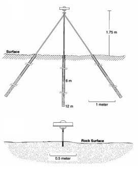
Monumentation
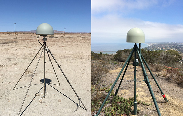
Long records of pre-GPS geodetic measurements including spirit leveling and electronic distance measurements have indicated significant temporal correlations (“colored” noise) that over time result in positional uncertainties that are higher than would be expected with just random (“white”) noise, which is primarily due to instrumental noise. The temporal correlations are primarily attributed to the instability of geodetic monuments caused by soil contraction, desiccation, or weathering, e.g., by expansive clays in near-surface rocks. Based on this earlier geodetic record, a special monument was designed by the PGGA (Bock et al., 1997) and SCIGN (Hudnut et al., 2011) projects for crustal deformation monitoring, in order to reduce non-tectonic local surface deformation. The monument consists of five deeply-anchored drill-braced stainless steel rods, one vertical and four slanted (~10 m) rods, isolated from the surface down to ~3 m. The SCIGN monument has been adopted by other geophysical networks, including PBO and parts of BARD. Also, developed and installed at numerous stations were less expensive shallow-braced monuments that were particularly suitable in rock outcroppings. Thus, the bulk of the SCIGN and PBO stations are well anchored. Less expensive and supposedly less stable monuments have been incorporated, in particular in the early years of continuous GPS (cGPS), including rock pins, pillars, masts and building mounts.
Centering and Leveling
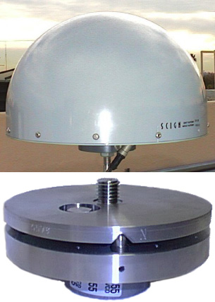
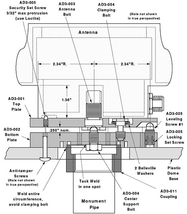
Centering of the GNSS antenna is another important factor for achieving mm-level accuracy, especially re-centering when an antenna is replaced. For this purpose, the SCIGN project designed a precision antenna adapter with leveling capabilities. The adapter is permanently welded at the meeting point of the four slanted and one vertical rods that make up the monument. The GPS antenna is then mounted on a standard 5/8 inch threaded bolt. The SCIGN project also developed two types of protective antenna covers (“radomes”), short and tall. The adapters and radomes have been installed for nearly all cGPS stations in western North America.
Antenna Heights
The SCIGN adapter has leveling and centering capabilities and a fixed “antenna height” (0.0083 m) above a clearly defined point within the adapter, which serves as the Geodetic Reference Mark (GRM) to which published station coordinates refer. Thus, the GRM is 0.0083 m below the Antenna Reference Point (ARP) – in this case the bottom of the chokering antenna, the standard at all geophysical stations. This ensures that an antenna change at a station will not introduce any artificial offsets in position. Not all stations have this arrangement so antenna heights above the GRM may vary from zero (when there is no adapter, in this case equivalent to the ARP), to several meters.
The SOPAC database maintains a complete record of relevant metadata and metadata changes, and is a critical resource for the accuracy of the geodetic datum. For example, to determine the monument and antenna height for a SCIGN/PBO station, access the IGS site log or the SOPAC Site Information Manager (SIM). A complete list of receivers and antennas is provided by the IGS.
SCIGN Monument ERP
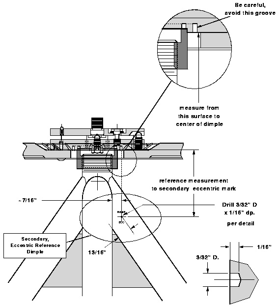
The SCIGN monument also has an eccentric reference point (ERP) that is a drilled mark on the north-facing monument leg. It is used for two purposes: to provide a secondary measurement if the adaptor is removed from the monument and to provide surveyors a point to easily level to the monument without disturbing the antenna. The distance from the ERP to the geodetic reference point is determined by adding the distance from the ERP to the bottom of the antenna adaptor (typically 0.1016m; listed as the "antenna adaptor divot distance" in the Monument section of the site log) PLUS the distance from the bottom of the antenna adaptor to the top of the center support screw (0.02286 m): 0.1016 + 0.02286 = 0.12446 m. Surveyors leveling to a SCIGN monument’s ERP should keep in mind that this height is x meters (0.12446 m in the example above) below the published antenna height.
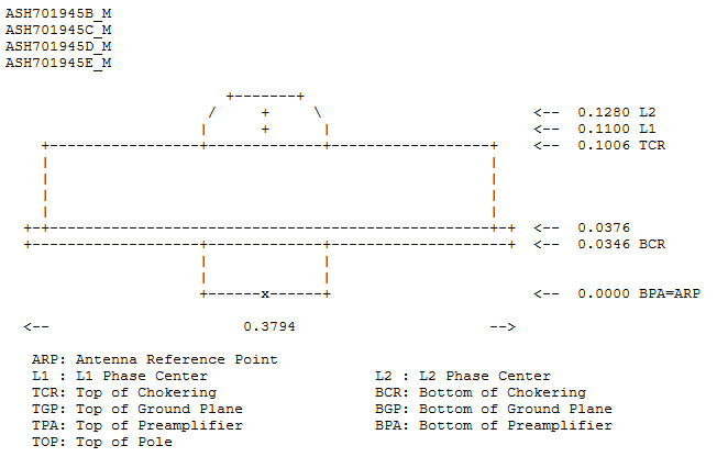
Antenna Phase Centers
For precise geodetic applications, it is also necessary to clearly identify the L1 and L2 antenna phase centers and their exact relationship to the ARP, both horizontally and vertically. IGS Absolute phase center offsets and variations with and without radomes are estimated by single robot-mounted calibration by collecting thousands of observations at different orientations (e.g., Rothacher, 2001). This information is also maintained in tables available from the NGS.
References
Bock Y., S. Wdowinski, P. Fang, J. Zhang, S. Williams, H. Johnson, J. Behr, J. Genrich, J. Dean, M. van Domselaar, D. Agnew, F. Wyatt, K. Stark, B. Oral, K. Hudnut, R. King, T. Herring, S. DiNardo, W. Young, D. Jackson, and W. Gurtner (1997), Southern California Permanent GPS Geodetic Array: Continuous measurements of crustal deformation between the 1992 Landers and 1994 Northridge earthquakes, J. Geophys. Res., 102, 18, 013-18,033.
Hudnut, Kenneth W, Yehuda Bock, John E Galetzka, Frank H Webb, and William H Young. 2001. "The southern California integrated GPS network (SCIGN)." In The 10th FIG International Symposium on Deformation Measurements, 19-22. Orange California, USA.
Rothacher, M. (2001), Comparison of absolute and relative antenna phase center variations. GPS Solutions 4(4): 55-60.