
![]()
![]()

Geodetic Module and MEMS Accelerometer Package
- Seismogeodetic Monitoring Overview
- System Overview
- TThe GM Connector Panel
- Configuration for Operation
- Connecting to a GNSS Receiver
- Verifying Operation
- SIO MEMS Accelerometer
- SIO MEMS Accelerometer Specifications
- Geodetic Module Real-Time Streaming Formats Accelerations (and Meteorological) Data
- SOPAC Seismogeodetic Data Flow
1. SEISMOGEODETIC MONITORING OVERVIEW (view document as a pdf here)
Seismogeodesy is the optimal real-time integration of high-rate GNSS and seismic sensors. Applications include earthquake and local tsunami warning and rapid response systems, and structural health monitoring. To this end, SIO has developed, in house, a system to upgrade existing GNSS stations or to establish new seismogeodetic stations, specifically for earthquake and local tsunami early warning and structural health monitoring. The system consists of an SIO Geodetic Module and MEMS accelerometer package (GAP) described below. The Geodetic Module is also able to support GNSS meteorology with the addition of the SIO MetSensor.
2. SYSTEM OVERVIEW
The SIO Geodetic Module (GM) is a low-power, microprocessor-based, internet appliance running application specific firmware. It does not contain a standard OS and will only perform specific embedded functions.
In operation, the GM receives the 1 PPS signal and RTCM3 serial (RS-232) data from any attached GNSS receiver that provides the RTCM3 messages (at least messages 1004, 1006, 1008, 1012, 1033). The RTCM3 data are packed into a TCP/IP stream and served to one (and only one) recording client connected via TCP port 50000. If the GNSS receiver being used is the Trimble NetR9, the TCP client must also set (via command) the GNSS week in the GM as the RTCM3 stream from the standard NetR9 (without the “Advanced RTCM” option) does not include the GNSS week (message type 1019). The GM requires the GNSS week in order to time-stamp internal SOH (state-of-health) records as well as any internally recorded/archived data (e.g. during communications outages).
As the GM receives precise timing and 1 PPS from its attached GNSS receiver, it can also accurately record external sensors. At present, the GM supports three external sensors; the SIO MEMS Accelerometer, the SIO MetSensor and any of the Vaisala Corporation’s “WXT” family of weather transmitters. If used, the WXT sensor must be connected to the GM’s AUXILIARY connector as that port offers full-duplex RS-232 communications and provides unregulated power for the sensor. The data acquired via the AUXILIARY port are then served to a recording client via TCP port 50004.
Any combination of the SIO sensors (Accelerometer or MetSensor) can be connected to any of the GM’s SEN1, SEN2 or SEN3 ports. These ports provide unregulated power to the connected SIO sensor and use long-wire RS-422 (differential) communications. The data acquired via the SEN1, 2 or 3 ports are served to a recording client via TCP ports 50001, 50002 and 50003, respectively. Again, only one TCP client can be connected to TCP port at a time.
A highlight summary of the GM features includes:
- Operates from 9-18 VDC. Consumes a total of 1 watt with one SIO Accelerometer attached.
- Requires only one IP address.
- Provides three ports (SEN1,2,3) for any combination of SIO sensors (MEMS Accelerometer or MetSensor).
- Offers the AUXILIARY port for the Vaisala Corporation’s “WXT” family of weather transmitters.
- Serves real-time data streams from the connected GNSS receiver, MEMS accelerometer and meteorological sensors via TCP/IP to individual recording clients.
- Supports telnet for remote status and management as well as operation configuration changes.
- Utilizes ftp for remote firmware updates as well as data extraction (archived sensor recordings and SOH).
3. THE GM CONNECTOR PANEL
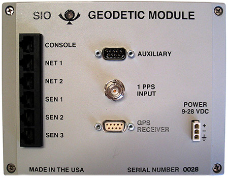
The LED in the upper left corner is bi-color (red or green) and will illuminate green for one second, turn off for three seconds and repeat indicating normal operation. A blinking or solid red is an indication of failure.
The various type and function of each of the GM’s front panel connectors are described below. None of these connectors are waterproof.
3. Console
RJ45 jack. This is NOT an Ethernet port. Instead, this port is a full-duplex RS-232 communications port and serves as the user’s interface during initial configuration or whenever communicating with the unit locally. The port is fixed at 115200 bps, no parity, 8 data bits, 1 stop bit and no flow-control. Although the connection cable is a standard RJ45 plug -to- RJ45 plug network cable, the custom “serial adapter” supplied is required for communications with an RS-232 terminal.
Net1
RJ45 jack. This is a standard 10BASE-T Ethernet port capable of optionally sourcing unregulated PoE power (as a PSE) to a passive PoE device (PD). When enabled, the PoE voltage is the same as the GM’s input power and is not conditioned. The maximum PoE power consumption allowed is 750mA @ 12 VDC.
WARNING – If this port has been configured to “NET1 Mode = PoE”, never connect a non-PoE compatible device as damage to that non-PoE device may occur.
Net2
RJ45 jack. This port is reserved for future implementation and must be configured as “NET2 Mode = disabled”.
Sen1
RJ45 jack. This port provides three individual RS-422 communications circuits along with unregulated power for use by the SIO family of sensors (MEMS Accelerometer and MetSensor). The RS-422 circuit pairs are “TRANSMIT” (from GM), “RECEIVE” (to GM) and “1PPS” (from GM). The remaining pair carries the same power as the GM’s input power and is not conditioned but is controlled (off/on) by the GM. The maximum power consumption allowed from this port is 750mA @ 12 VDC. Data collected via this connector are served to a TCP client on port 50001.
Sen2
RJ45 jack. This port provides three individual RS-422 communications circuits along with unregulated power for use by the SIO family of sensors (MEMS Accelerometer and MetSensor). The RS-422 circuit pairs are “TRANSMIT” (from GM), “RECEIVE” (to GM) and “1PPS” (from GM). The remaining pair carries the same power as the GM’s input power and is not conditioned but is controlled (off/on) by the GM. The maximum power consumption allowed from this port is 750mA @ 12 VDC. Data collected via this connector are served to a TCP client on port 50002.
Sen3
RJ45 jack. This port provides three individual RS-422 communications circuits along with unregulated power for use by the SIO family of sensors (MEMS Accelerometer and MetSensor). The RS-422 circuit pairs are “TRANSMIT” (from GM), “RECEIVE” (to GM) and “1PPS” (from GM). The remaining pair carries the same power as the GM’s input power and is not conditioned but is controlled (off/on) by the GM. The maximum power consumption allowed from this port is 750mA @ 12 VDC. Data collected via this connector are served to a TCP client on port 50003.
Auxiliary
DE9M. This connector offers a full-duplex RS-232 communication port for various uses. The port supports three handshake controls; CD (in), DTR (out) and CTS (in) but none are required. The communication rate is programmable to either; 1200, 2400, 4800, 9600, 19200, 38400, 57600 or 115200 bps. The default is 9600 bps. When enabled, this port can also source power. The voltage is the same as the GM’s input power and is not conditioned but is controlled (off/on) by the GM. The maximum power consumption allowed from this port is 750mA @ 12 VDC. When one of the Vaisala Corporation’s “WXT” family of weather transmitters is connected to this port and the port configuration is set by the operator to be “Aux Mode = WXT meteorological” with “Aux Power = on”, the GM will poll the sensor for a sample every 10 seconds. Data collected via this connector are served to a TCP client on port 50004.
1 PPS Input
BNC jack. This connector accepts the one pulse per second timing signal from a collocated GNSS receiver and is required for GM operation. The rising edge of the 1 PPS signal is expected to be “on time” and the maximum voltage is 5 VDC.
GNSS Receiver
DE9F. This connector contains a full-duplex RS-232 communication port for communication with the attached GNSS receiver. The port supports three handshake controls; DSR (out), RTS (in) and CTS (out) but none are required. The communication rate is programmable to either; 1200, 2400, 4800, 9600, 19200, 38400, 57600 or 115200 bps. The 115200 bps rate is recommended. Data collected via this connector are served to a TCP client on port 50000.
Power 9-18 VDC
3-pin (TE/AMP Mini-Universal MATE-N-LOK). This is the GM’s primary power input and chassis connection. This power input is protected internally by a series, one-time fuse (1 amp, time-delayed) followed by over-voltage clamping circuitry. The connector’s three contacts are POWER, RETURN and CHASSIS and the power input pigtail cable supplied is arranged RED, BLK and WHT, respectively.
WARNING - Some GMs power input connector are erroneously labeled “9-28 VDC”. Do not apply an input voltage >18 VDC or damage will occur.
4. CONFIGURATION FOR OPERATION
Although the GM has been pre-configured for your application, there remain a few unique parameters that still need to be set via the GM’s CONSOLE port.
- Using the CONSOLE cable (RJ45-RJ45 network cable with the “serial adapter” attached), connect one RJ45 plug to the GM’s CONSOLE jack then connect the DE9F end to an RS-232 terminal or a computer with terminal emulation via an RS-232 serial port. Set the terminal to 115200 bps, N, 8, 1 with hardware flow = OFF. Ready the terminal (launch the terminal emulation program) and apply 12VDC power to the GM. A display similar to the one below should appear.
Welcome to the SIO Geodetic Module, Version V3.43 at ????
STATUS
CURRENT CONFIGURATION
MODIFY CONFIGURATION
MONITOR
TOOLS
RESERVED
- Move the selection (black highlight) to “MODIFY CONFIGURATION” using the keyboard arrows then press RETURN (ENTER). A display similar to the following will appear.
Station Name ????
NET1 Mode: normal
NET2 Mode: disabled
GNSS Baud Rate: 115200
GNSS archived to CF: YES
SOH archived to CF: NO
SEN1: accelerometer , Short Line sample rate=100 s/s
SEN2: disabled , Short Line
SEN3: disabled , Short Line
AUX : disabled power=OFF, baud rate=9600 , sample rate=10
TIME: seconds from RTCM3, week from any TCP client
Press ESC to return to Main Menu
- Give the GM a proper name for its installed location. With the selection on “Station Name...” press RETURN. When prompted for a new name, type the actual name (case sticky, recommend 4 characters maximum) followed by RETURN then answer “Y” if acceptable.
- Configure the GM’s IP network parameters. Using the keyboard arrows, move the selection down to “NET1...” and press RETURN. The response will be:
NET1 Mode: normal
As we want “normal”, there is no need to change the “NET1 Mode” so press RETURN again to skip this parameter and move on to the next parameter which is “IP”. The response will be similar to:
IP: ???.???.???.??? Enter new IP:
Enter the actual network IP in decimal format followed by RETURN then “Y” if acceptable. The response will then be similar to:
GatewayIP: ???.???.???.??? Enter new IP:
Enter the actual network gateway IP in decimal format followed by RETURN then “Y” if acceptable. The response will then be similar to:
Subnet Mask: 255.255.255.??? Enter new Mask:
Enter the actual network gateway IP in decimal format followed by RETURN then “Y” if acceptable. The response will then be similar to:
IP: ???.???.???.???
GatewayIP: ???.???.???.???
Subnet Mask: ???.???.???.??? OK[Y/N]:
Review the summary of the three entries. If a correction is required, answer “N” and repeat this step entirely. If all are correct, answer “Y” and the display will respond as:
Station Name ????
NET1 Mode: normal
NET2 Mode: disabled
GNSS Baud Rate: 115200
GNSS archived to CF: YES
SOH archived to CF: NO
SEN1: accelerometer , Short Line sample rate=100 s/s
SEN2: disabled , Short Line
SEN3: disabled , Short Line
AUX : disabled power=OFF, baud rate=9600 , sample rate=10
TIME: seconds from RTCM3, week from any TCP client
Press ESC to return to Main Menu
- Press ESC to return to the main menu then select “CURRENT CONFIGURATION” to review all changes. That display will be similar to:
Station Name ????
NET1 Mode: normal
IP: ???.???.???.???
GW: ???.???.???.???
Mask: ???.???.???.???
MAC: 0.80.194.40.???.???
NET2 Mode: disabled
IP: ???.???.???.???
GW: ???.???.???.???
Mask: ???.???.???.???
MAC: 0.80.194.40.???.???
GNSS Baud Rate: 115200
GNSS archived to CF: YES
SOH archived to CF: NO
SEN1: accelerometer , Short Line sample rate=100 s/s
SEN2: disabled , Short Line
SEN3: disabled , Short Line
AUX : disabled power=OFF, baud rate=9600 , sample rate=10
TIME: seconds from RTCM3, week from any TCP client
Press ESC to return to Main Menu
NOTE – The MAC addresses for the Ethernet ports “NET1” and “NET2” are programmed during assembly and cannot be changed by the operator.
- If all settings appear proper, press ESC to return to the main menu. This completes the minimum configuration for operation.
5. CONNECTING TO A GNSS RECEIVER
It is now time to connect the GNSS receiver to the GM. This is straightforward for most GNSS receivers through the serial port on the GM CONNECTOR PANEL described in section 3.
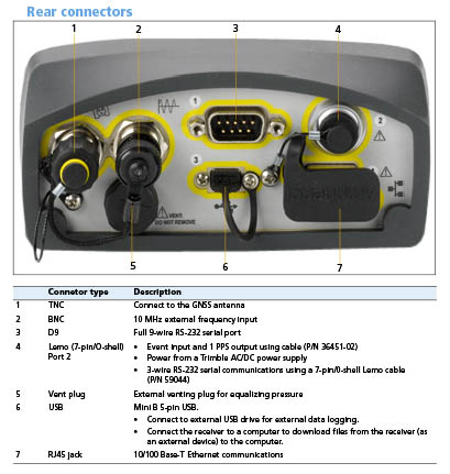
The Trimble NetR9 receiver requires special treatment, which is described now. The custom cable supplied will be necessary to supply power to the receiver as well as provide access to its serial data (port 2) and 1PPS signal - all of which are contained in the single NetR9 connector (item #4 below).
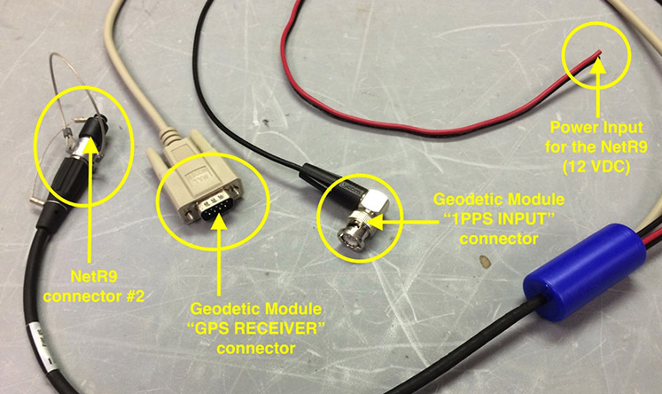
Configure the NeR9 to output RTCM on Serial 2 with Baud=115200, Parity=N and Flow=Disabled. Unless the receiver has the “Advanced RTCM” option installed, the RTCM measurement rate will be 1 Hz and is not adjustable.
6.VERIFYING OPERATION
Once the GNSS receiver has been connected to the GM, connect an SIO MEMS Accelerometer (using supplied 60-foot cable) to the GM’s “SEN1” connector then from the main menu, select “STATUS”.
Welcome to the SIO Geodetic Module, Version V3.43 at ????
STATUS
CURRENT CONFIGURATION
MODIFY CONFIGURATION
MONITOR
TOOLS
RESERVED
A display similar to the following will appear with updates each second:
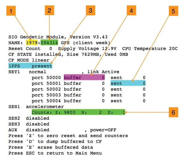
The critical status items to observe are:
Item #1
This field is the GNSS week. The NetR9 does not transmit the week so the TCP client must send it to the GM whenever establishing a TCP socket connection with port 50001, 2, 3 or 4. If this field is zero, then the TCP client has yet to connect (or set) the current week. Once set, the GM will then keep track of the week (until power is removed).
Item #2
This field is the GNSS seconds of the week. This value is extracted from the RTCM3 stream transmitted by the GNSS receiver and will increment each second once after the receiver has achieved adequate satellite lock. If this field is stagnant, there is an absence of satellite lock or RTCM3 connection or the RTCM3 stream is being transmitted a baud rate that does not match that set in the GM.
Item #3
This displays the status of the 1 PPS connection with the GNSS receiver. Its two states are simply “present” or “absent”. The signal must be present for the SIO Accelerometer to operate.
Item #4
This is a counter of the number of data packets buffered into the GM’s memory waiting to be transmitted to the TCP client. If this counter is zero (or hovering around zero), then the client is connected and packets are flowing. If this counter is increasing, then either the client is not connected or the communication path is losing too many packets. The operator may erase these buffered data by typing “E” at any time while in this screen.
Item #5
This is a counter of the number of data packets that have been sent to the TCP client. If this counter is stagnant, the TCP client is not currently connected. In normal operation this counter should be continuously incrementing. The operator may zero this counter by typing “Z” at any time while in this screen.
Item #6
This field displays the raw sample counts (mm/s^2) from each of the accelerometer’s axis outputs. When the sensor is rolled over, these values should change accordingly. NOTE– The SIO MEMS Accelerometer reports raw acceleration. Under normal orientation, the vertical axis will typically report 1g (not 0g like some other manufacturers’ devices). This approach allows the SIO Accelerometer to be mounted in any orientation such as “vertically” (on a wall) or upside down (on a ceiling).
Conclusion -
In general, if all six status fields above display normal as described, the system is functional.
7.SIO MEMS ACCELEROMETER
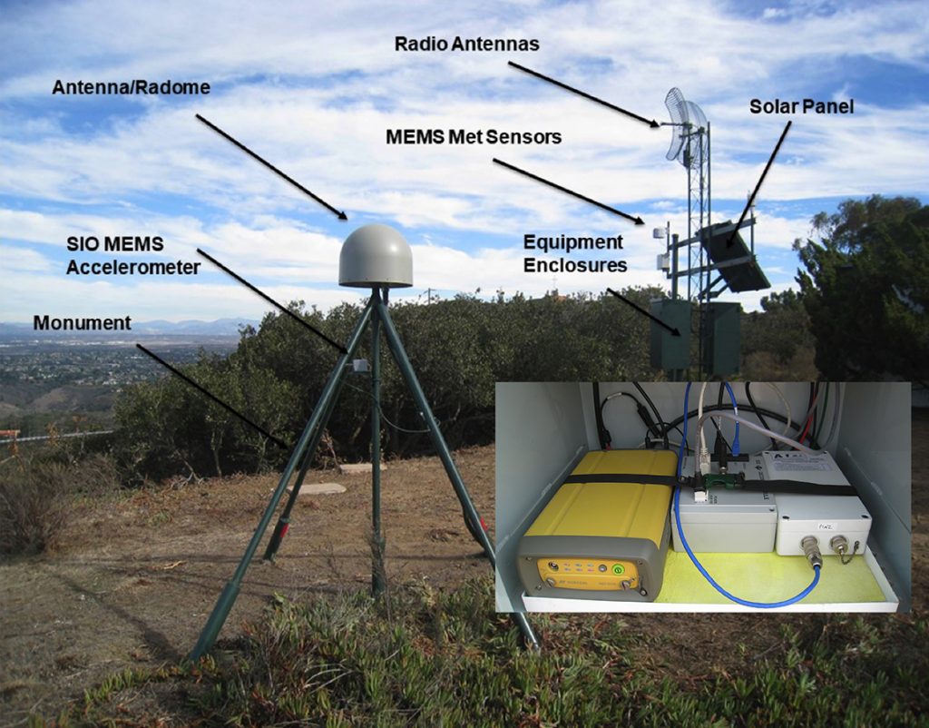
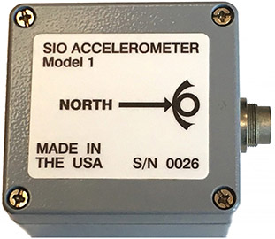
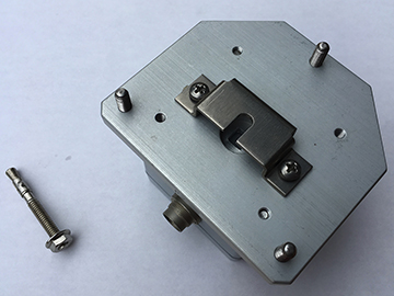
The SIO MEMS Accelerometer is a +/-2g, 16-bit, low power, waterproof, low cost, three-axis, undamped acceleration sensor. The unit can be mounted in any orientation including to round pipe up to 2 inches (51 mm) in outside diameter.
The device operates in concert with the SIO Geodetic Module (GM). Over a single, outdoor rated CAT5 (4 pair, 24 AWG) cable, the GM supplies power, timing and communications for the accelerometer. The cable attaches to the accelerometer’s housing via a single waterproof 8-contact circular locking connector. The cable connection to the GM is completed by a single RJ-45 plug that mates to any of the GM’s three sensor input ports as shown below.
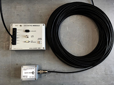
The communications interface consists of three RS-422 channels supporting cable lengths in excess of 300 feet (100 meters). The accelerometer receives commands including the time-of-day as well as a 1 PPS (pulse-per-second) timing signal from the GM sourced by the GM’s attached GNSS receiver. This information is required by the accelerometer’s microprocessor to precisely control the sample acquisition timing and determine the time-stamp applied to the collected samples. The output sample rate is presently set to 100 s/s.
NOTE – All three acceleration axes report true acceleration. With that, when mounted normally on a horizontal surface, the Z (vertical) axis data will report 1g when at rest. Those data are not converted to display 0g when quiescent.
|
|
|
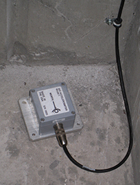 Horizontal Surface Mount
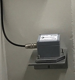 Vertical Wall Mount
 |
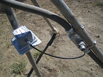 |
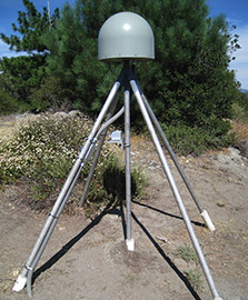
| Vertical round pipe on a SCIGN Monument | |
| SIO MEMS Accelerometer Anchor Installation and Leveling | |
|
|
|
 |
 |
- Identify an installation location within the distance of the accelerometer cable.
- Mark a compass direction to the mounting surface for eventual alignment of the accelerometer.
- Using a rotary hammer drill and a 1/4" diameter masonry bit, drill a single hole to the precise depth of 1.7 inches.
- Clean the hole out with a vacuum or compressed air.
- Hammer in the wedge anchor in until 1/2” remains.
- Test fit the accelerometer.
- With the accelerometer’s leveling feet (screws) adjusted to “minimum”, slide the accelerometer’s bottom bracket onto the anchor under the anchor’s hex nut.
- Adjust the nut on the anchor until it just clears the accelerometer’s bracket.
- Orient the accelerometer so that the NORTH arrow points north.
- Place the bubble level from the tool set on the accelerometers base plate (not its cover). Use the hex screwdriver from the tool set to adjust the leveling feet (only two should need to move) until the unit is level while maintaining proper directional orientation.
- Use a 7/16” wrench to tighten the anchor’s nut until it captures the stainless-steel mounting bracket on the accelerometer securely.
END
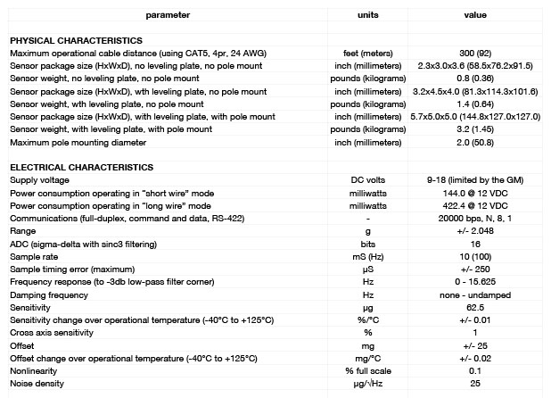
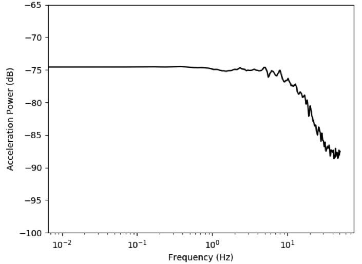
SIO MEMS ACCELEROMETER SPECIFICATIONS
9. GEODETIC MODULE REAL-TIME STREAMING FORMATS ACCELERATIONS (AND METEOROLOGICAL) DATA
The formats of two types of real-time streams that are output from the SIO Geodetic Module: Meteorological (MT) and Accelerometer (AC) are described here. The initial section of the header is the same for each type, but the expansion area contains type-specific terms following the initial section.
Note that:
- Checksum is XOR for each 2 byte value in the header and data block following the total message length value in the header.
- Data is BigEndian
- Default sample rates are:
Accelerations: 100 Hz
GPS: 1 – 5 Hz
Meteorological: 10 sec
Header Block
| Term | Num bytes | Type | value/comment |
| Sync | 2 | Hex | Hex bytes equal to ACAB |
| Checksum | 2 | Int | |
| Total Message length | 2 | Int | |
| Data type | 2 | Char | AC or A4/MT/GP/SH for Acceleration, Meteorological, GPS and State of Health datatypes |
| GPSweek | 2 | Int | Weeks since 00:00:00 UTC 6 January 1980 |
| GPSmillisecs | 4 | int | Milliseconds since the beginning of the week |
| Site ID | 8 | Char | Null terminated string |
| Header expansion area length | 1 | Int | |
| For Accelerometers | |||
| Header version | 1 | Int | |
| Multiplier | 4 | Int | That was used for conversion made from counts to values in datablock |
| Divider | 4 | Int | “ |
| Sample rate | 2 | Int | In hundredths of a sec |
| Number of channels | 1 | Int | 3 for multiplexed acc |
| Format code | 1 | Int | 1 = mm/s/s multiplexed (accel) |
| Maximum value | 2 | Int | 2048 |
| Number of samples | 2 | Int | Currently 100 for accel; 1 for met |
| For Meteorological | |||
| Header version | 1 | Int | 2 |
| Number of samples | 2 | Int | 1 |
Data block
| For Accelerometer | Repeated number of samples | ||
| Z (vertical) | 2/4 | See format code above for units
2 bytes for AC, 4 for A4 |
|
| NS (north-south) | 2/4 | Int | “ |
| EW (east-west) | 2/4 | Int | “ |
| For Meteorological | |||
| String from sensor | Variable length (~65 bytes | Char | SOPAC uses Ta, Ua, Pa |
Meteorological raw format from sensor, e.g.:
0R0,Dm=163D,Sm=0.2M,Ta=22.7C,Ua=49.4P, Pa=1.0110B,Rc=0.00M,Hc=0.0M
Dm = wind direction average (degrees)
Sm = wind speed average (meter/second)
Ta = temperature (Celsius)
Ua = relative humidity (%RH)
Pa = pressure (bar)
Rc = rain accumulation (mm)
Hc = hail accumulation (hits/cm2h)
We will only be reporting Ta, Ua and Pa in the data block (at least for now)
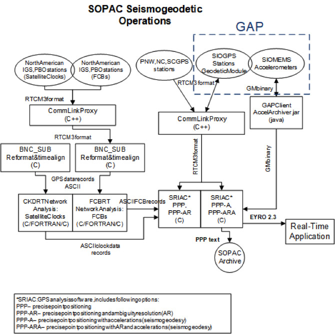
10.SOPAC SEISMOGEODETIC DATA FLOW
The graphic below shows the flow of GNSS and accelerometer data from the SIO Geodetic Module and MEMS Accelerometer(GAP) package to the precise point positioning (PPP) analysis modules, and then output to a real-time applications (e.g., earthquake early warning)in EYRO 2.3 format. The GNSS data are output in RTCM3 format. The accelerometer data are retrieved by the GAP Client. The format for the accelerometer data is given in Section 9.